The relationship between sting balances and multi-axis transducers
An Interview with Kevin Copleston, one of the founders of Sensor Solutions Ltd
Sensor Solutions: ‘So a multi-axis load cell is really?’
Right well, it depends.
I’ll make a simple 3 axis to show what you want. Here’s a ships propeller shaft:
Engine, gearbox, propeller shaft, down to the end, and there’s a propeller on the end, and it’s supported in bearings.
First think, ‘I want to measure how much thrust I have’, so that gives a compression in the propshaft.
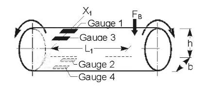
At this measurement point here, I going to measure thrust.
So within the shaft I’m going to use a strain gauge at 1, and a strain gauge at 2, and one opposite at 4, and finally one opposite the first at 3.

Creating a wheatstone bridge, 1, 2, 3, 4,
To explain, push a rubber in from each side, what happens, gets narrower side-to-side, but gets fatter top-to-bottom.
So what happens is, one and three resistance goes up, as the thrust force compresses the shaft and the gauges shorten, and the reaction is a compression, so 3 and 4 resistance would go down as the shaft gets fatter, stretching the gauges, and these are two Poisson ratios.
Poisson’s ratio is dependent on material, valid for the material elastic deformation. For metal’s it is around 0.3.
The exact calculation is, for the compression in the shaft (thrust generated):

With a shaft in compression a contraction will occur. In the transverse direction, a transverse expansion will occur. From this, a change of resistance will be found in strain gauge 1. For strain gauge 2, the difference will be . This will be true of strain gauges 3 & 4 respectively.
With the strain gauges connected in indices sequence to form a full bridge the output signal will be:

So these 2 and 4, by Poissons ration go up a little bit, so here you get 2.6 times the output of a single strain gauge, but you only measure the reaction to the thrust of the blade.
So we’ve got thrust now, but how much power does that require?
Measuring Torque in the Shaft
So I want to measure torque in the shaft.
So what we do here is mount strain gauges at 45 degrees, and on the other side at 45 degrees.
If the shaft’s turning, shear goes up and down, so on this side it’s going up, and on that side it’s going down.
Strain is spiralling round the shaft, meaning strain gauge 1 is in tension, and strain gauge 3.
Then 2 and 4 are in compression. So let’s number it 1,2,3, 4,
(remember it’s got to go up, down, up, down, 3 and 4)
So, as the engine pumps, there’s resistance from the prop, there’s power, and that shows itself as torque in the shaft, torque is related to power, power consumed (equals) torque reaction.
We have our output due to torque, one side goes up, and one side goes down, we get an output of 4 times, as opposed to 2.6 times in a full wheatstone bridge.
The exact calculation is, for the torque in the shaft:

Under clockwise torque, strain gauges 1 and 3 will be under compression and 2 and 4, tension. For strains absolute values are the same, so all values of strain can be calculated with the equation:

Measuring the Bending Moment in the Shaft
So we’ve now got to do a measurement of pure torque, right? So that’s two components.
Ah now, say we’ve got a, from the back of the flywheel there’s a slightly eccentric, on the back of the prop shaft, so as it goes round the prop shaft is doing that, it’s spinning as well, it’s putting a bending moment on that shaft. Because, if this bearing was slightly mis-aligned then as that went round it would be putting a bending moment on, so if we want to measure bending moment here, that would probably be a UJ, but the bearing here would have quite a high bending moment, and you’re worried about fatigue in shaft, and the effects of a misalignment of the bearing, because that’s easily done, as you’re screwing the thing down if you’ve got something out of place.
So we are interested in bending close to there.
We would instrument the shaft in bending, so we would have gauges top, and bottom, where these two in tension, these two are in compression, so 1, 2, 3, 4, round the wheatstone bridge, that needs to go up, so 1 and 2 go down, so now, if we measure thrust down there, all of them would go up, so they cancel out, so this is only measuring bending moment as it rotates.
You’ve managed to get to measure bending moment.
The exact calculation is, for the bending moment in the shaft:
So the strain absolute on the upper side and underside values on the shaft are the same, but with the opposite sign.
So:

The sign of the strain value is positive on the side in tension and negative on the side in compression.
So 3 components you’ve measured now, but if this bearing is up and that bearing is down, giving this effect, so the shaft is doing that, we’re having shear in this component, OK, because it’s being pushed up and down in the shaft. So now I want to measure here the shear component.
So this is bending and that’s shear. I want to measure the shear component on the shaft which has, you have 45 degrees shear here, but you can imagine you are shearing a shaft like this, say it’s misaligned this way, principal strains (?), both sides are up.
In this case it’s spiralling round, in this case it’s, er, if it’s going down this side and this side are, that angle’s in tension, and this is compression. And on this side it’s in compression.
So around the bridge, again we’ll just number it, er, what we do is draw out wheatstone bridge, remember it’s got to go up and down, so one is going up, 2 is going up as well, 3 is going down, and 4 is going down. So you just put the gauges in the bridge where you need them, and again, because this is 45 degrees it will see no thrust or bending and because now if I put torque on that the pattern is the other way on the other side, it’s mirrored on the other side, it will cancel out.
So we can isolate force, torque, bending, and shear. We can isolate our forces and moments.
There’s a component.
6 components we then start looking at…, what are the components? Look at an aeroplane, what are you interested in there?
Lift, drag, thrust, weight, yaw and pitch.
So you’ve got movement like this, like this, like this, (etc) and yaw like this, so you’d be interested in measuring torque in that plane, and torque in that plane. That’s where your 6 components come from.
Building these multi-axis strain gauge are mega-money. This is very simple, because you’ve only got one bar, but for (?) the other two components your trying to measure, you’d have to machine this very, very specially to be able to, and you can spend 30k just on the machining, say spark eroding of a 6 component sting balance. What goes on the back of a model aeroplane is a thing called a sting balance and it measures all those components.
They are mega bucks, you very rarely buy those things, you generally only buy them once.
Sensor Solutions: ‘So they are especially made for each job, and require special fabrication?’
Yep, but out in the real world you are only really interested in, the guys are usually only interested in measuring torque, load, like that prop shaft, using a torque transducer, unless you want something like, you want to measure the load in the engine mounts, like this sort of thing, you generally only buy a single component, a transducer. These multi-axis component transducer are very, very expensive. Very, very difficult to design where by when you put yaw on you don’t see any other parameter, (indistinct) bridge, picking that up, what we call cross talk.
Sensor Solutions: ‘So sting balance, its an arm that connects to an item you are measuring, like in a wind tunnel, as you did one in a submersible?’
Yes but that was only two components, sorry four components. It’s, er, um, I was looking at thrust and drag, and bending, and bending…..er, looking at bending this way, and bending that way.
Three components really.
That was just measuring the vane and the bending on the shaft and the amount of drag on the shaft.
Generally when you are looking at ship work, …
Sensor Solutions: ‘Was that a sting you used on the submersible?
No wasn’t really a sting, it was a multi-component balance.
A sting is where you put the model on the end, on the submersible I er…
There’s the submersible there and there’s the vane, and in that little interface there I had to measure, the amount of angle, would give an upward force or a down ward force, there was also drag this way, the faster you go the more the drag on the planes, so you use shear for that, and then this part would be in bending, then I’d use the parallelogram measurement for this measurement and this measurement, and likewise that measurement. So they were interested in this, this, this, and that, as there’s a load on the end of the beam that wants to go back.
But that’s not a sting balance, that’s just a multi-component balance, using a structure to measure multiple forces, by clever use of the Wheatstone bridge. And when you’re making ships, when you have a ship on a model and its going through the water running, that only tends to be a few components.
It’s only aircraft and things where you’re interested in 6 components.
Sensor Solutions: ‘They are moving free in air so you have to measure all the forces…’
Yes, and when you are in the transition stage sub-sonic to super-sonic, in that transition period there are some very complex forces (?) going on and things aren’t operating as normal (?) and they need to understand the transitioning forces, they use very high-speed cryogenic wind tunnels which are very expensive, and because it’s cryogenic you’ve got this temperature change so the shell has to be perfectly balanced as well as isolating a force and a moment.
Information about: Wide Range of Uses | High Levels of Accuracy